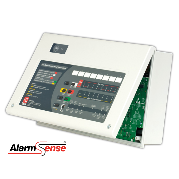
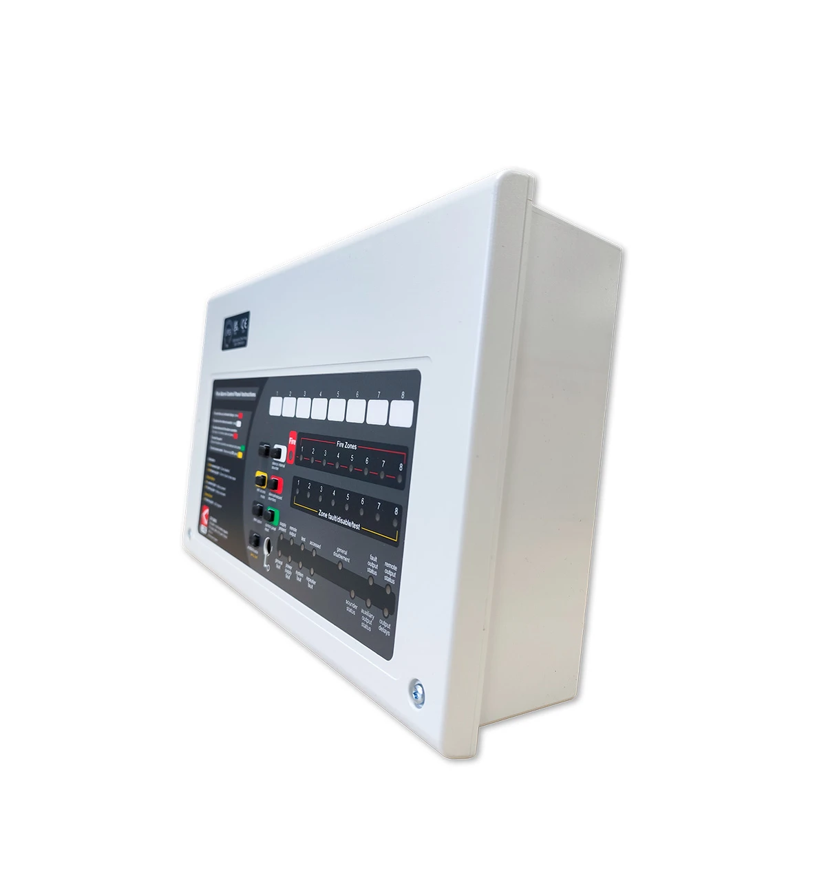
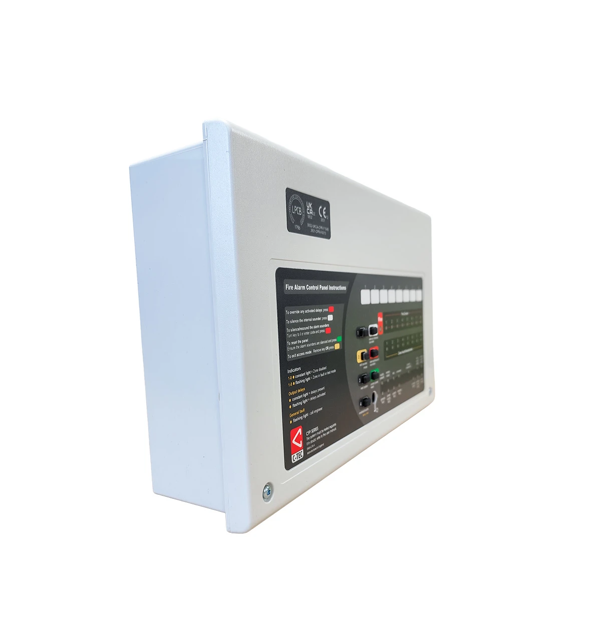
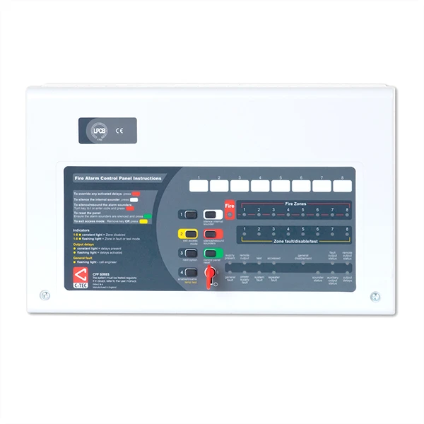
| CFP AlarmSense 2 Zone Two-Wire Fire Alarm Panel | CFP AlarmSense 4 Zone Two-Wire Fire Alarm Panel | CFP AlarmSense 8 Zone Two-Wire Fire Alarm Panel |
Approvals/certifications | Certified to EN54-2 & 4 by the LPCB. | Certified to EN54-2 & 4 by the LPCB. | Certified to EN54-2 & 4 by the LPCB. |
Mains supply | 230V 50/60Hz. | 230V 50/60Hz. | 230V 50/60Hz. |
Mains rated current | 350mA maximum. | 350mA maximum. | 350mA maximum. |
Internal power supply | 19V-28.5V (27V nominal). Ripple 7V maximum (battery fault). | 19V-28.5V (27V nominal). Ripple 7V maximum (battery fault). | 19V-28.5V (27V nominal). Ripple 7V maximum (battery fault). |
Total output current limited to | 1.5A @ 230Vac (ImaxA eq 146mA). | 1.5A @ 230Vac (ImaxA eq 146mA). | 1.5A @ 230Vac (ImaxA eq 146mA). |
Quiescent current | 25mA (mains failed, internal sounder active, PSU & gen fault LED lit) | 25mA (mains failed, internal sounder active, PSU & gen fault LED lit) | 25mA (mains failed, internal sounder active, PSU & gen fault LED lit) |
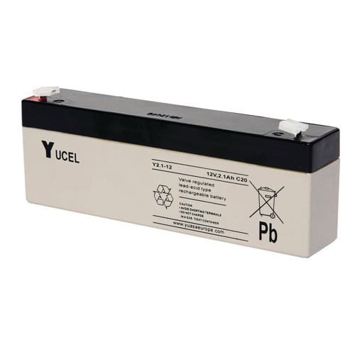
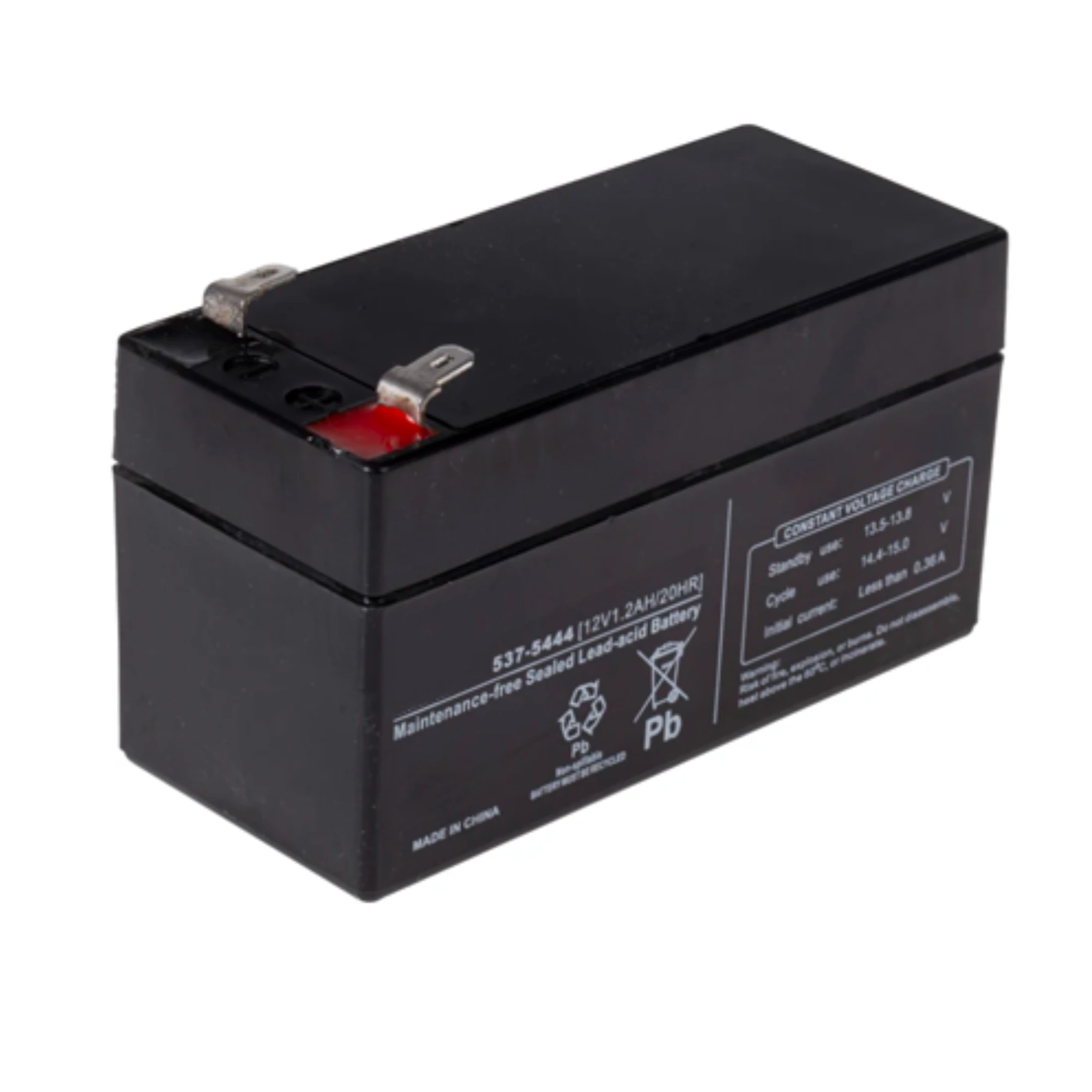
Max battery size and type | 2 x 12V 3.2Ah VRLA connected in series. Min. battery size 1.2Ah. | 2 x 12V 3.2Ah VRLA connected in series. Min. battery size 1.2Ah. | 2 x 12V 3.2Ah VRLA connected in series. Min. battery size 1.2Ah. |
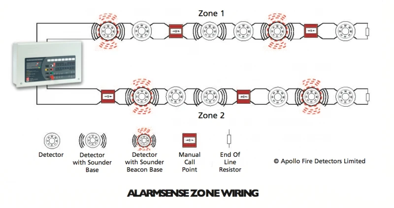
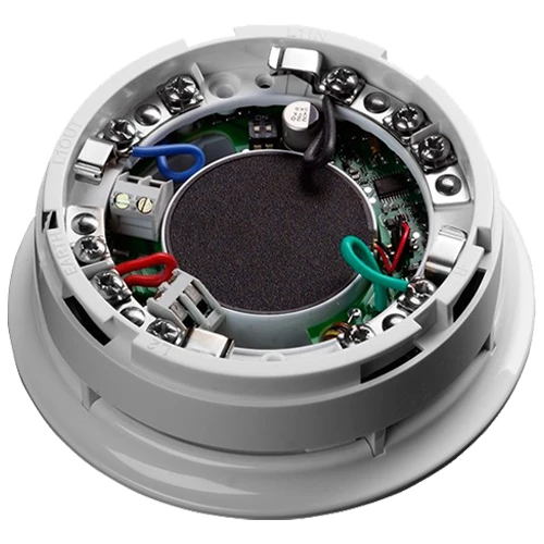
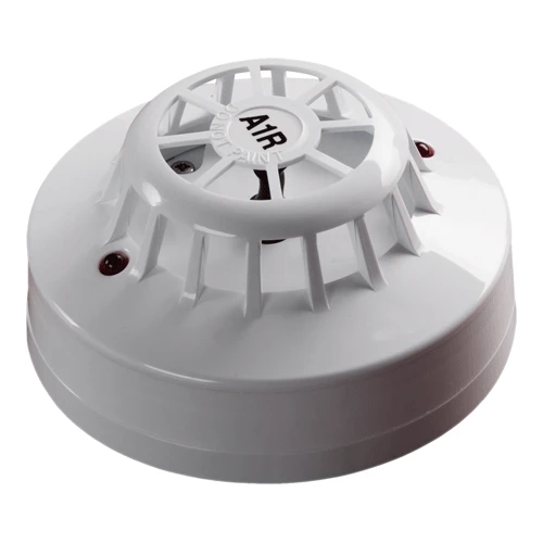
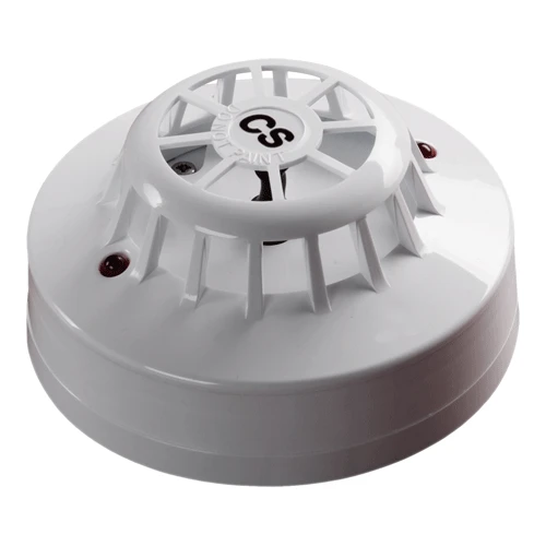
No. of detector zone circuits | The CFP702-2 has 2 AlarmSense zone circuits which are compatible with Apollo's AlarmSense range of detectors & call points AND sounders & visual indicators. (Max. length per circuit is 500m). | The CFP704-2 has 4 AlarmSense zone circuits which are compatible with Apollo's AlarmSense range of detectors & call points AND sounders & visual indicators. (Max. length per circuit is 500m). | The CFP708-2 has 8 AlarmSense zone circuits which are compatible with Apollo's AlarmSense range of detectors & call points AND sounders & visual indicators. (Max. length per circuit is 500m). |
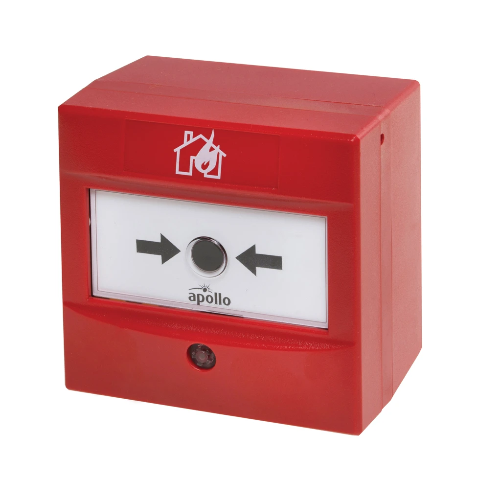
Call point resistor value | Only use AlarmSense call points. | Only use AlarmSense call points. | Only use AlarmSense call points. |
Max. devices per detector zone | 25 AlarmSense detectors/manual call points per AlarmSense zone. For AlarmSense sounder limitations per AlarmSense zone see 'Max. sounder output current' section. | 25 AlarmSense detectors/manual call points per AlarmSense zone. For AlarmSense sounder limitations per AlarmSense zone see 'Max. sounder output current' section. | 25 AlarmSense detectors/manual call points per AlarmSense zone. For AlarmSense sounder limitations per AlarmSense zone see 'Max. sounder output current' section. |
No. of conventional sounder circuits | 4 – these are additional conventional (non-AlarmSense) sounder circuits; Max. length per circuit is 500m. | 4 – these are additional conventional (non-AlarmSense) sounder circuits; Max. length per circuit is 500m. | 4 – these are additional conventional (non-AlarmSense) sounder circuits; Max. length per circuit is 500m. |
EOL resistor value | 6800Ω 5% Tol. 0/25W (blue, grey, red, gold). | 6800Ω 5% Tol. 0/25W (blue, grey, red, gold). | 6800Ω 5% Tol. 0/25W (blue, grey, red, gold). |
Alarm voltage | 27V max, 20V min (final battery voltage) | 27V max, 20V min (final battery voltage) | 27V max, 20V min (final battery voltage) |
Auxiliary relays | Two: (1) Aux. Fire; (2) Fault. Volt free single pole changeover. Max. switch current 1A; Max. switch voltage 30Vdc. | Two: (1) Aux. Fire; (2) Fault. Volt free single pole changeover. Max. switch current 1A; Max. switch voltage 30Vdc. | Two: (1) Aux. Fire; (2) Fault. Volt free single pole changeover. Max. switch current 1A; Max. switch voltage 30Vdc. |
Open collector outputs | Two: (1) Reset (Active during reset cycle); (2) Remote (Active during any unsilenced fire condition provided all relevant delays have expired). Max. sink current 30mA, Max. open circuit volt | Two: (1) Reset (Active during reset cycle); (2) Remote (Active during any unsilenced fire condition provided all relevant delays have expired). Max. sink current 30mA, Max. open circuit volt | Two: (1) Reset (Active during reset cycle); (2) Remote (Active during any unsilenced fire condition provided all relevant delays have expired). Max. sink current 30mA, Max. open circuit volt |
Other outputs | 24V Aux. Power (Protected by a resettable fuse. 100mA min. hold current. Resets when fault removed). | 24V Aux. Power (Protected by a resettable fuse. 100mA min. hold current. Resets when fault removed). | 24V Aux. Power (Protected by a resettable fuse. 100mA min. hold current. Resets when fault removed). |
Auxiliary inputs | Two: (1) ‘Class Change’ (constant sounders); (2) Alert (pulsed sounders). Connect to 0V to trigger, Max. input voltage 27V (non-latching) | Two: (1) ‘Class Change’ (constant sounders); (2) Alert (pulsed sounders). Connect to 0V to trigger, Max. input voltage 27V (non-latching) | Two: (1) ‘Class Change’ (constant sounders); (2) Alert (pulsed sounders). Connect to 0V to trigger, Max. input voltage 27V (non-latching) |
Engineer (AL3) functions | Program coincidence (double knock); Invoke One Man Walk Test; Program delays; Set up zones for non-latching operation; Program sounders to resound (or not resound) | Program coincidence (double knock); Invoke One Man Walk Test; Program delays; Set up zones for non-latching operation; Program sounders to resound (or not resound) | Program coincidence (double knock); Invoke One Man Walk Test; Program delays; Set up zones for non-latching operation; Program sounders to resound (or not resound) |
Expansion connections | Yes – for optional network driver cards (one required per repeater system), relay output cards and EN54-13 sounder circuit interface boards. | Yes – for optional network driver cards (one required per repeater system), relay output cards and EN54-13 sounder circuit interface boards. | Yes – for optional network driver cards (one required per repeater system), relay output cards and EN54-13 sounder circuit interface boards. |
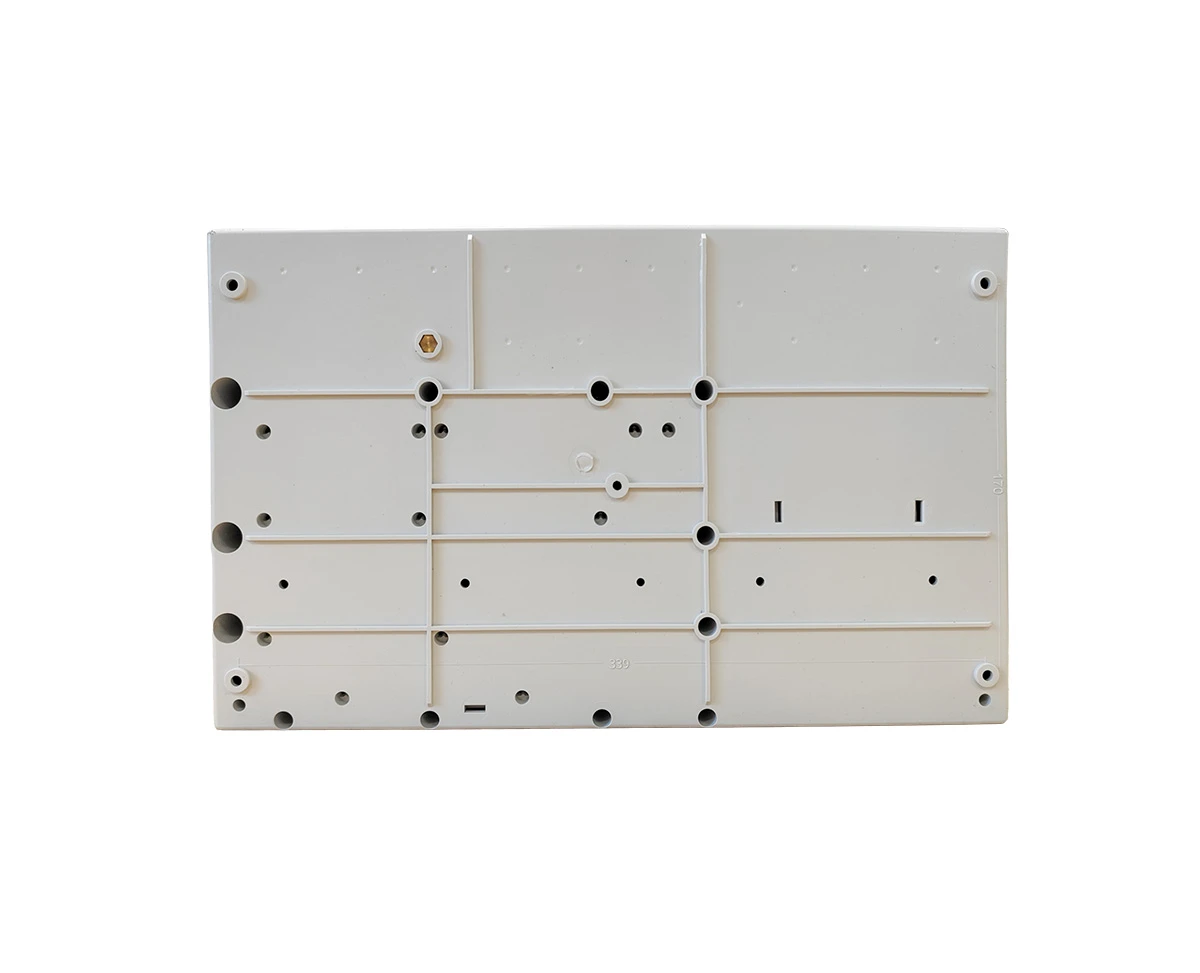
Product dimensions (mm) | 380 W x 235 H x D 96mm (hole required for flush mounting = 367 W x 220 H x 75 D mm. No bezel required). | 380 W x 235 H x D 96mm (hole required for flush mounting = 367 W x 220 H x 75 D mm. No bezel required). | 380 W x 235 H x D 96mm (hole required for flush mounting = 367 W x 220 H x 75 D mm. No bezel required). |
Construction & finish | Plastic lid and base; RAL7035 textured | Plastic lid and base; RAL7035 textured | Plastic lid and base; RAL7035 textured |
IP Rating | IP30. | IP30. | IP30. |
Weight | 1.75kg (without batteries) | 1.75kg (without batteries) | 1.75kg (without batteries) |